Saturday, April 16, 2016

REFERENCE ELEMENTS used in catia

Reference element is the features that have no mass and volume are used only to assist we in the creation of the models. They acts as a reference for drawing a sketches for features, defining the sketch plane, placing placed features, assembling components, creating sketched based feature, and so on.

REFERENCE PLANES

The features are generally not created on a same plane; therefore we need to select the other defaults planes are creating new planes to be used as a sketching plane for other feature.

Default Planes :- There are three Default Planes as given bellow:-

1.      XY plane

2.      YZ plane

3.      ZX plane

Creating a new plane

Toolbar: Reference Elements > plane

Planes are used as the sketching plane for drawing sketches for the sketch-based features, Appling references to the placed features, and so on. 
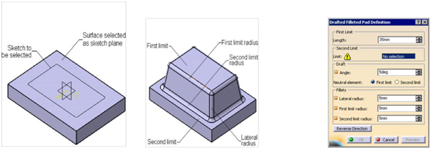
The sketch of the based feature is generally drawn using one of the default planes as the sketching planes. After creating the based feature, we can select one of its paces as the sketching plane to draw the sketch for the other-based 
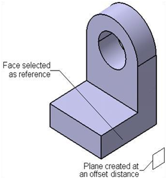
features. However sometimes we may need to draw a sketch on a plane, which is add one offset distance from the planner face of the base feature.


To create a new plane chooses the plane tool from the reference element (extended) toolbar.
In CATIA V5, There are eleven different methods for creating new plans as given bellow:-

Creating a plane at one offset from an existing plane/planner face

When we invoke the plane definition dialog box and select plane to offset from plane type on dialog box. Select the plane or the planar face from which the offset plane need to create now we can set the value of offset distance from the offset spinner, we can also specify the number copies of the new plane in instance(s) spinner and then ok.
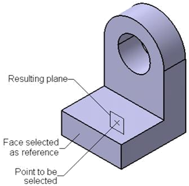
Creating a plane parallel to an existing plane and passing through a point

The parallel through point option in the plane type drop down list is used to create an offset plane that is parallel to reference plane or planar face and passes through specified point.

To create a plane, select the parallel through point option from the plane type, select a plane or planar face from the geometry area and select a point. Select point or vertex from geometry area and then choose OK.

Creating a plane at an angle/normal to a plane

The angle/normal to plane option in the plane type drop–down list is used to create a plane at an angle to a reference plane or face. We can also create a plane normal to the selected plane or face. To create a plane using this option, select the angle/normal to plane option from the plane type drop-down list; we will be prompted to select the rotation axis. Select an edge of the model, sketched line, or axis from the geometry area that will be used as the axis of rotation; we will prompted to select the reference plane. Select the reference or plane or planar face from the geometry area such that the rotation axis and the selected reference plane are parallel to each other; the preview of the plane is displayed set the value of rotation angle in the angle spinner. To reverse the direction of the plane creation, specify a negative angular value. Next, choose the ok button from the plane definition dialog box. If we choose normal to the plane button from the plane definition dialog box, a plane will be created normal to the reference plane. We can also create multiple copies of the plane using the repeat object after ok check box. If we select the project axis on reference plane check box the resultant plane will be created in the reference plane by projecting the rotation axis over the reference plane.
Creating a plane through three points

The through three points in a plane type drop down list is used to create the plane passes through selected points. On selecting this option, we will be prompted to select the first point Vertex, or an endpoint of a line from the geometry area. On doing so, we will be prompted to selected the second point. Select the second point from the geometry area. Similarly select the third point; choose ok button from the plane definition dialog box the resulting plane will be displayed.
Creating a plane through lines

The Through Two Lines option in the plane type drop-down list is used to create a plane that will be passes through selected lines, edges, or an edge a line. When we select this option we are prompted to select the first line. Select an edge, sketch line, or an axis from the geometry area; we will be prompted to select the second line. After we select the second line the preview of the plane will be displayed choose the Ok button from the plane definition dialog box.

Creating a plane through a point and a line

The Through point and a line option in the plane type drop-down list is used to create a plane that passes through a point and a line. When we select this option, we will be prompted to select this point, we will be prompted to select a point. Select a point through which we want the plane to pass; we will be prompted to select a line. Select a line, axis, or edge from the geometry area through which the plane will pass; the preview of the plane will be displayed in the geometry area. Choose the Ok button from the plane definition dialog box.


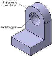
Creating a plane through a planar curve

The Through planar curve option is used to create a plane that will be coplanar to be selected arc. To create a plane using this option, select the through planar curve option plane type drop-down list; we will be prompted to select the curve. Select the curve from geometry area. We will notice that the preview of the plane is placed coplanar to the selected curve. Choose

OK from the plane definition dialog box.
Creating a plane normal to a curve

The Normal to curve option is used create plane that is normal to a selected curve. On selecting this option, we will be prompted to select a reference curve. Select the curve from the geometry area; the preview of the normal plane, placed of the midpoint of selected curve, is displayed. Note that, by default the midpoint the selected curve is considered as a point to place the plane normal to curve. If we do not want create a plane in the middle of the selected curve, select appoint on a curve/vertex/edge where the plane will be placed. Next, choose the Ok button from the plane definition dialog box.

Creating a plane using an equation
The equation option is used to create using the equation Ax + By + Cz=D, where the values of A, B, C, and D are variable and can change to modify the orientation of the plane. When we select this option the plane definition dialog box will expand and the A, B, C, and D spinners will be displayed. We can set the values in these spinners to create a plane using the above mentioned equation. The normal to compass button in this dialog box is used to create a plane normal to the compass. The parallel to screen button is used to create a plane normal to the current view of the screen. After specifying the parameters, choose the ok button from the plane definition dialog box.

Creating a plane using mean through points

The mean through point option is used to create a plane at an orientation defined by the mean of the selected points. On selecting this option, we will be prompted to select points. Select the required points or vertices from the geometry area. The name of the selected points and vertices are displayed in the points display box in the plane definition dialog box. The preview of the plane created with its orientation depending on the mean of the selected point, is displayed in the geometry area. Choose the Ok button from the plane definition dialog box.

Create a plane tangent to a surface

The tangent to surface option is used to option create a plane tangent to selected surface and passing through a selected point. On selecting this option, we will prompted to select the reference surface. Select a point, tangent to selected surface, is displayed. Choose ok button from the plane definition dialog box.

THANK YOU,,,,,,,,,,,,,,,,,,,,,,,,,,,,,,,
FOR MORE INFORMATION please contact facebook


Friday, April 15, 2016

catia educational report of CREATING BASE FEATURES AND DRESS FEATURE IN PART DESIGN WORKBENCH

CREATING BASE FEATURES AND DRESS FEATURE IN PART
  
            DESIGN WORKBENCH:-


Creating Base Features by Extrusion


The Pad tool is one of the most widely used tools top create the base features. To a base feature using this tool, draw the sketch and exit the Sketcher workbench. Then, choose the down arrow on the right of the Pad tool in the Sketch-Based Features toolbar; the Pads sub-toolbar will be displayed. Select the Sketch then choose the Pads sub-toolbar; the sub-toolbar; Pad Definition dialog box will be displayed, we will be enter promoted to enter the required data to modified the pad. Also the name of selected sketch will be displayed in the Selection display box and the preview of the pad feature will be display in the geometry area. Set the value of the depth in the length spinner.

Creating Base Features by evolving Sketches

to create the revoled feature , draw the sketch that will be revolvsd aroun the centre line, also known as axis. Next, exist the sketcher workbench and choose the Shaft button from sketch based features toolbar; the Shaft Defination dialog box will be displayed, also the preview of the shaft feature using the default parameters will displayed in the geometry area.

The name of the sketch will be displayed in the Selection display box of the profile/Surface area. By default, the first angle spinner will displays 360deg. Therefore, the sketch revole by 360deg. We can also set the angular values of the first angle and second angle spiner to define the angle in the first and second directions. Note that the sum of the angles must be equale to or less than 360deg angle.we can also Reverse direction button and thin shaft features from the shaft defination dalog box.


Creating Drafted Filleted pad Features

We can create an extruded feature having drafted faces and filleted edges using the Drafted filleted Pad tool. To create this feature, draw the sketch and exit sketcher workbench. Then

Menubar: Insert > Sketch-Based Feature > Drafted filleted pad

Toolbar:     Sketch-Based feature > Pad-sub toolbar > Drafted filleted pad.

On doing so the Drafted filleted pad definition dialog box will be displayed, next we need to specify a reference for a second limit, now select the sketching plane on which the sketch is drawn as the second limit; and preview the extruded feature is displayed in geometry area. Set the value of depth of the extrusion in the length spinner. Specify the value of drafted angle in the angle spinner and then Ok.

Creating Multi-pad based features

The Multi-pad tool to create a extruded feature in which we can specify different extrusion depths in each closed loop in the sketch. To draw Multi-pad feature

Menubar: Insert > Sketched-Based feature > Multi-Pad

Toolbar:     Sketch Based feature > pads-sub toolbar > Multi-Pad.


Note:- We can also create Pocket based feature as pad based features.


Thursday, April 14, 2016

CREATING BASE FEATURES AND DRESS FEATURE IN PART DESIGN WORKBENCH

Creating Base Features by Extrusion


The Pad tool is one of the most widely used tools top create the base features. To a base feature using this tool, draw the sketch and exit the Sketcher workbench. Then, choose the down arrow on the right of the Pad tool in the Sketch-Based Features toolbar; the Pads sub-toolbar will be displayed. Select the Sketch then choose the Pads sub-toolbar; the sub-toolbar; Pad Definition dialog box will be displayed, we will be enter promoted to enter the required data to modified the pad. Also the name of selected sketch will be displayed in the Selection display box and the preview of the pad feature will be display in the geometry area. Set the value of the depth in the length spinner.
Creating Base Features by evolving Sketches

to create the revoled feature , draw the sketch that will be revolvsd aroun the centre line, also known as axis. Next, exist the sketcher workbench and choose the Shaft button from sketch based features toolbar; the Shaft Defination dialog box will be displayed, also the preview of the shaft feature using the default parameters will displayed in the geometry area.

The name of the sketch will be displayed in the Selection display box of the profile/Surface area. By default, the first angle spinner will displays 360deg. Therefore, the sketch revole by 360deg. We can also set the angular values of the first angle and second angle spiner to define the angle in the first and second directions. Note that the sum of the angles must be equale to or less than 360deg angle.we can also Reverse direction button and thin shaft features from the shaft defination dalog box.
Creating Drafted Filleted pad Features

We can create an extruded feature having drafted faces and filleted edges using the Drafted filleted Pad tool. To create this feature, draw the sketch and exit sketcher workbench. Then

Menubar: Insert > Sketch-Based Feature > Drafted filleted pad

Toolbar:     Sketch-Based feature > Pad-sub toolbar > Drafted filleted pad.

On doing so the Drafted filleted pad definition dialog box will be displayed, next we need to specify a reference for a second limit, now select the sketching plane on which the sketch is drawn as the second limit; and preview the extruded feature is displayed in geometry area. Set the value of depth of the extrusion in the length spinner. Specify the value of drafted angle in the angle spinner and then Ok.


Wednesday, April 13, 2016

CATIA educational report

DRAWING SKETCHES IN THE SKETCHER WORKBENCH-1

Most components designed using CATIA V5-R19 are a combination of sketched features, placed features, and derived features. The placed feature is created without drawing a sketch whereas the sketched features require a sketch that defines its shape.

The sketcher workbench provides the space and tools to draw sketches of the solid model. Generally, the first sketch drawn to start the decision is called the base sketch, which is then converted into a base feature. However, once we gate familiar with the advanced option of CATIA V5, we will also be able to use a drive feature or a derived part as the based feature.

To draw a sketch, invoke the sketcher workbench in the part design workbench or the assembly design workbench by closing the sketch tool from the sketcher toolbar. Next select a plane to draw a sketch. Draw the sketch and proceed the part design or wireframe and surface design workbench to convert it into a solid model or surface model.

Starting with new file

Choose part design from Start > Mechanical design; we will enter into a part design workbench and new part dialog box will be displayed, enter the part name and select Enable hybrid design radio button and then ok to start new file workbench in part design workbench.
Invoking the sketcher workbench using the sketch tool.


To invoke the sketcher workbench using the method, choose the sketch tool from sketch. Select a plane from three default planes in the specification tree of from the geometry area the sketcher workbench will be invoked and the selected plane will be oriented parallel to the screen. We will be prompted to select an object or command.
SETTING THE SKETCHER WORKBENCH


Modifying Units

To modify units, invoke the Options General option to expand the tree.


from Tool menu. Next, click on the + sign the left of the Choose the parameter and measure option and then


choose the units and then Ok.
TOOLBARS

There are various standard toolbars and buttons that appear in the workbenches of CATIA V5. These toolbar are discussed next.

Standard Toolbar

This toolbar is common in all workbench of CATIA V5.
The tools in this toolbar are used to start anew file, open a existing file, save a file, and print the current documents. These buttons are also used to cut and place the selection and temporary clipboard, copy a selection, paste the content from the keyboard to the selected location, undo, redo, and invoke the help topics. What’s this? Provides help on the toolbar icons.

Part Design Workbench Toolbars

We can invoke the part design workbench by choosing the new button from stander toolbar and selecting part from new dialog box displayed. Alternatively we can choose

Start>Mechanical Design>Part Design from the menubar. The toolbar in the Part design workbench are discussed next.

View toolbar

The button in the view toolbar are used for manipulating the view of the model using the tool such as pan, zoom, normal viewing about a planar surface, face of plane, defining a render style and so on. It is available on the all workbenches.

...............................................thanks..................................................


basics of catia

CATIA  (Computer  Aided  Three  dimensional  Interactive  Application),  developed  by

Dassault Systems, is one of the world’s leading CAD/CAM/CAE packages. Being a solid modeling tool, it not only unites the 3D parametric features with 2D tools, but also addresses every design-design-through-manufacturing process. Besides providing an insight into the design content, the package promotes collaboration between companies and provides them an edge over their competitors.

In addition to creating solid models, sheet metal components, and assemblies, 2D drawing can also be generated in the Drafting workbench of CATIA. The drawing views that can be generated include orthographic, section, auxiliary, isometric, and detail views. We can also generate model dimension and create reference dimensions in the drawing views. The bi-directionally associative nature of this software ensures that the modifications made in the model are reflected in the drawing views and vice versa.

It is exceptionally easy to use and state of the art user interface, CATIA V5 delivers innovative technologies from maximum productivity and creativity, from the inception concept to the final products. CATIA V5 reduces the learning curve, as it allows the flexibility of using feature based and parametric designs.

CATIA provides three basic platforms: P1, P2, and P3 and P3, P1 is for small and medium sized-process- oriented companies that wish to grow toward the large scale digitized product definition. P2 for the advanced design engineering companies that required product, process, and resources modeling. P3 for the high-end design applications and is basically Automotive and Aerospace industry where high quality surfacing or class-A surfacing is used. The subject of interpretability offered by CATIA V5 includes receiving legacy data from the other CAD systems and from its on product data management modules. The real benefit is that the links remains associative. As a result, any change made to this external data gets notified and the model can be updated quickly.

CATIA V5 WORKBENCHES

CATIA V5 serves the basic design tasks by providing different workbenches as a specified environment consisting of a set of tools that allows the user to perform specific design tasks. The basic workbenches in CATIA V5 are Part design, Wireframe and Surface design,


2

Assembly Design, Drafting, Generative Sheet metal Design, DMU Kinematics, and Free

Style.

Part Design Workbench

The part design Workbench is a parametric and feature-based environment in which we can create solid models. Basic requirement for creating a solid model in this workbench is sketch is drawn in the sketcher workbench that can be invoked within the part design workbench we can draw the sketch using the tool in this workbench while drawing the sketch, some constraints are automatically applied to it. We can

Also apply additional constraints and dimensions manually. After drawing the sketch exit the sketcher workbench and convert it into a feature. The tools in the part design workbench can be used to convert the sketch into a sketch-based feature. This workbench also provides other tools to apply the placed features such as fillets, chamfers and so on. These features are called the Dress-up features.


Wireframe and surface Design Workbench

The wireframe and surface design workbench is also a parametric and feature based environment, and is used to create wireframe and surface models.

Assembly Design workbench

The Assembly design workbench is used to assemble the components using the assembly constraints available in the workbench. There are two types of assembly design approaches:

1. Bottom-up                                                                               2. Top-down

In the bottom-up approach of the assembly design, the components are assembled together to maintain their design intent. In the top-down approach, components are created inside the assembly in the Assembly Design workbench.

Drafting Workbench

The Drafting Workbench is used for the documentation of the parts or assemblies created earlier in the form of drawing views and their detailing. There are two types of drafting techniques:

1. Generative drafting                                                               2. Interactive drafting

3


The generative drafting technique is used to automatically generate the drawing views of the parts and assemblies. The parametric dimension added to the component in the part design workbench during its creation can be generated and display automatically in the drawing views. The generative drafting is bi-directionally associative in nature. We can also generate the Bill of material (BOM) and balloons in the drawing views.

Generative Sheet metal Design Workbench

The Generative Sheet metal Design workbench is used for the designing of the sheet metal components. Generally, the solid model of the sheet metal components are created to generate the flat pattern of the sheet, study the design of the dies and punches, study the process plan of the designing. The workbench also provides the tools needed for manufacturing the sheet metal components.

DMU Kinematics Workbench

The DMU kinematics workbench is used to design mechanism by adding joints between the components. It also allows we can simulate and analyze the mechanisms dynamically.

GTTING STARTED WITH CATIA V5-R19

Install CATIA V5-R19 on system and then start it with double-clicking on its shortcut icon display on the desktop of computer. After the system has loaded all required file to start CATIA V5-R19, a new product file, with the default name product1 will start.

.............................................................thank you.....................................................................................

MADE EASY NOTES FOR MECHANICAL ENGINEERING FOR GATE 2017

                          MADE EASY NOTES FOR MECHANICAL ENGINEERING DESCRIPTION:-   This is handmade  made easy notes for mech...